I wanted to control my first camera station with a two channel radio control system from a toy. With one channel I wanted to select the function and with the other one I wanted to do the function like turn, tilt the camera and release the shutter of the camera. After modification on the receiver I could work with usual servos. During test flight I had no success to control the camera station.
The radio control system works with 27 Megacycles and AM. With a height of about 5m the receiver got more signals from citizen band as from the transmitter. The problems will increase with the height of the system.
Then I bought a new radio control system (GRAUPNER 40Megacycles FM) and I had no problems to control the camera station. This system provides seven channels for future modifications. At the time I used only a switch for the shutter release an the tilt is shown directly by a potentiometer on the transmitter.
To release the shutter of the camera (only photo) it is possible to use an electronical switch. It is better to use a relay to close the camera contacts. With direct connection between camera circuit and circuit of control system there may be problems. If a electrical shutter releas is not possible you can use a mechanical solution like a servo pushing the buttom of the camera.
Some reflex cameras could be released by a wire. The other end of the wird can be fixed to a servo to release the shutter from ground control.
With horizontal turning the camera system taking photos from different directions are possible. Most times a working range of 360 degrees is needed. Usually servos have a smaller working range. You have to do some modifications to use the servo for endless turning. Turning the camera station should be done slowly. With fast turning it needs a time to get the system stable again.
With changing the vertical direction you can make photos from straight ahead to straight downwards to ground. This working range of 90 degrees is solved from most servos. If the camera is not to heavy it is no problem to fix the camera carrier directly to the servo. If the tilt is without control it should be fixed at about 15 to 20 degrees downwards from straight ahaed. In that way you will get a photo with few sky and most parts of landscape.
With turning the camera on the camera carrier you can change the image orientation from landscape to portrait (only useful with photo). This control can be done by a standard servo.
Radio control systems need a power supply with 4.8 volt done with four cells. In cold weather or with used batteries the voltage may decrease and the remote control makes problems.
To solve this problems I increased the amount of cells to 6 and I used a special voltage regulator.
Without a radio control system it is possible to use highe voltage than 4.8V. Integrated circuits of the 4000-CMos-Family work with voltage more then 12 volt.
Usually a servo works in a range of about 90 degrees. Sometimes this range is not big enough for special application (ie. horizontal direction of the camera-rig). To solve this problem, some servos can be modified to turn endless. A modified servo will turn in the chosen direction as long as you push the joystick of your RC-transmitter. It will work in both direction. In the neutral position of the joystick, the servo should not turn in any direction.
Dismount the servo-housing to get a view to the internal gear disks. If there is anywhere a half gear-disk, this servo cannot be modified for endless turning. If the gear does not work with the dismounted potentiometer, this servo cannot be modified, too.
The turning of the gear is limited mechanical by a stopper on one gear-disk. Most times it will be the last gear-disk. With cutting off the stopper the gear can turn further on. The housing of the servo can build together, so that the gear can work.
The next problem is the axis of the potentiometer. In some servos is a removeable clip for turning the potentiometer by the last gear disk. In other servos the potentiometer has to be removed completely. If the potentiometer can be used, it has to be set to the neutral position of the RC-transmitter. Fix the position by a tip of glue. If the potentiometer cannot be used, it has to be replaced by two fixed resistors. Read the value of the potentiometer and divide it by two. This will be the value of each fixed resistor. Most potentiometers have a value of 5k. So, the resistors may have a value of 2k4 or 2k7. Solder both resistors at one point together and connect it to the center-wire of the potentiometer. Connect the other points of the resistors to the other wires of the potentiometer. Check the neutral position of the RC-transmitter. If it does not work well, change the values of the resistors.
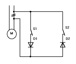
In some application it is nescessary to switch off the current of the servo-motor if a mechanical position is reached (ie elevation of the camera-rig or switching between landscape and portrait). The problem can be solved by using to switches on the mechanical positions to stop and two diodes to check the direction of the motor current. The switch has only to work in one direction of the turning. The other direction has not to be affected. This modification works on a standard servo and on a modified servo for endless turning.
The modification in the servo is easy to make. You need only these items:
Open the housing of the servo to get a view to the motor and the electronic circuit. Replace one wire between the electronic circuit and the motor by two wires and lead them outside of the servo-housing. The length of these wires depends on the positions of the switches. Connect the switches and the diodes as shown in the picture. Each diode controls one direction of turning. The motor has to turn in the direction until the switch is pressed. If the motor turns further on the direction of the diodes is wrong. Turn the diode and check the other direction in the same way on the other switch.
To avoid a reduce of motor-power, the diodes should be Schottky-Diodes (1N5817).
An ideal kite for lifting a camera system needs the following features:
There is no kite with all these features. You have always look for the best choice. Sometimes it is nescessary to use a special kite for a special weather condition. Every kite aerial photographer has got his own experiences which kite to use on special condition.
Cody (1.2m Spanwidth)
At first a tried to lift a camera system by a bought cody with a spanwidth of
1200 mm. Therfore he needs lot of wind. It is a stable flier with a large angle
of flight but it needs too much time to assemble.
Multiflare (Schimmelpfennig)
Next I tried a selfmade Multflare with a spanwidth of 3m from a book by Wolfgang
Schimelpfennig. It flies with a large angle of flight und have sometimes a
strong pull. The pull is always changing from to much until nothing. The time
for assembling is short. You have only to fix the spreader bar. In low wind
speed it is difficult to start the kite because of the extreme bridle position.
Rokkaku (2m height)
I tried a Rokkaku with a height of 2m. The time for assembly is longer because
you have to fix all bars. It is a stable flier up to the medium wind range with
a useful fling angle. Depending on the size you need enough wind for this kite.
Flowform (Jim Rowlands)
In spring 1995 I built a flowform with asize of about 2sq.m for kite aerial
photography. Soft kites have the advantage of small package size and a quick
start. The flowform flies stable in a wide wind range even with gusty winds.
The flying angle is useful and depends on the wind speed. With higher wind speed
I use a tail of 7m ribstop for more stabilization. Sometimes the kite directs a
to one side and moves very slow towards the ground.
Delta (6m span width)
For very low wind speed I made this delta with light ribstop. It has the
advantage of an easy start even without wind on the ground. With a small pull
on the line the delta starts to fly. Compared to other kites the delta is a bad
lifter because of a low angle of attack to the wind. Therefore you need a large
size for a useful lifter. Depending on the size this delta needs some time to
assemble.
Flowform (Am. Flowform 50 sq.ft.)
To get a more useful flowform in lower wind speed I built this kite with a size
of about 5 sq.m and a light ribstop. It flies even in low wind speed and is
more stable as the Rowlands flowform. The flying angle between 60 and 70 degrees
is perfect for kite aerial photography.
Other kite aerial photographers have similar experiences with thier kites for lifting camera systems. Thes kites are used for kite aerial photography, too:
Dopero (Double-Pearson-Roller)
Ralf Beutnagel has developed this kite for light wind. It looks like two
Pearson roller side by side. The Dopero flies stable with a large angle.
Double-Parasled
For the size of the kite it produces a large pull and is very useful to lift a
camera system. To start this kites is as quick as to start a soft kite.
Delta-Conyne
Many kite aerial photographers in the United States use this kite to lift camera
systems. It provides the combination of light wind flying by deltas with stable
flight of box kites.
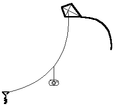
First the kite for lifting has to start and has to reach a height for stable flight. Then the camera system will be fixed into the kite line and all fixing has to be checked again. With giving more line carefully the camera station will reach the right height to take photos.
Start the kite and let out line until the kite reaches a height for stable flight. Then fix the system and let out more line until the camera reaches the right height. Depending on the pull of the kite it is possible to get problems with changing the height of the system.
Every type of kite has his own flight angle, which can be changed on some kinds by changing the bridle point. The angle of the kite line depends on length and weight of the line together with the wind speed, too.
With a high flying angle (over 45 degrees) the lift force is larger as the force by the wind. A load is easy to lift. With a low flying angle (less than 45 degrees) the wind force is larger as the lift force. It is more difficult to lift a load in the line. From ground to load there is a very low angle and from load to the kite is a larger angle.
Kites with a high flying angle have less lift force than kites with low flying angle. In example a delta has a low angle of attack to the wind and very low pull on the line. A Rokkaku with a large angle of attack flies with a low angle of line but with a lot of pull.
With a large flying angle it is easier to check the distance between camera and object. The best way for photos is to have a very short distance between camera and object.
For single line kites I prefer lines out of polyamid or polyester. They are cheap and their higher stretching save the kites in gusty winds. Because of the bigger diameter the handling with these lines are easier. But there are also disadvatages. They are heavy and in low winds it may be impossible to fly a kite. Strong lines (kevlar, spectra) have less stretching and in gusty winds the change of power affects the kites directly. On the other hand with those lines with smaller diameter can easier cut fingers.
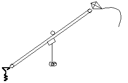
Flying lines swing in the power of the wind. If the wind speed increase, the swinging of the line will increase, too. At the fixing points (anchor on the ground and bridle point of the kite) is the movement of swinging very low. In the middle of the flying line will be the biggest movement of swinging. These movements are transfered over the suspension to the camera system and can affect taking photos. To defend swinging lines you can use thick rubber loops (fixings for car exhaust) which are fixed with sticks near the system in the flying line.
[ Index ] [ Contents ] [ Top of Page ] [ Next Page ]
©2015 Harald Prinzler