In 1989 during eastern holidays I bought my first steerable kite as an adult. Soon I liked to fly single line kites, too. I started to think about kite aerial photography in 1991 after reading an article of Michael Haugrund in the german kiefliers magazin Drachenmagazin (DraMa 8/91 page 8: Aufsicht). But it still needed one more year to finish the first camera station and in 1993 I shot my first aerial photos.
During the year I did not find much time for kite aerial photography. Other people have more success. Because of work I have to do it in the evening or at the weekend. The main point is the weather. If you have during the day good conditions, most time if you want to start the weather will be bad.
Nevertheless, after some time there are lots of experiences by own work and by information from other kite aerial photographers. This documentation shows the progress of my camera stations and the knowledge about aerial photography with kites.
Camera system
All parts needed to hold and control a camera is called camera system. It
may be built by several parts depending on the application.
Camera station
The camera station carry the used camera. A simple camera station may be only
a camera carrier. Depending on the demands the camera station has functions
for tilt, turn and release the camera.
Camera carrier
The camera carrier is part of the camera station, on which the camera is
mounted. A simple camera carrier is a ball socket where the camera direction
is fixed. To tilt the camera it is nescessary to control the camera carrier.
Suspension
With the suspension the camera station is fixed to the kite line. The camera
station should be as stable as possible.
Control system
The control system controls the function of the camera station for tilt, turn
or release the camera. With a remote control these function may be controlled
from ground.
Tilt
The tilt function changes the vertical view direction of the camera. With an
angle of 0 degrees the camera looks straight ahead. With -90 degrees the camera
looks straight downwards to earth and with +90 degrees straight upwards to the
sky.
Turn
The turn function changes the horizontal view direction of the camera. There
is no description for the direction.
Angle of object lens
The angle of object lens describes the field of view by the object lens
towards the object. It depends on the focal distance by the object lens.
A small focal distance has a large angle of view and a large field of view.
Field of view
The field of view describes all the dimensions what the camera sees depending
on angle of view and angle of object lens. A photo is just a copy of the
actual field of view.
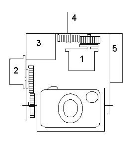
A general camera station holds the camera and has some functions to change the directions of the camera and to release the camera shutter. The positions for these control items depends on the size of the camera and the construction of the camera station. A camera station could be very small around one camera or large for several cameras and many functions.
Most times a camera station has functions to turn and tilt the camera and to
release the shutter of the camera. But there are more functions possible:

        1 - Servo to turn the camera
        2 - Servo to tilt the camera
        3 - Power supply
        4 - Fixing for the suspension
        5 - Receiver for radio control
The position of the items depend on the camera and the weight on the camera station. On small cameras aditional gear disks are not nescessary.
In the year 1992 I started with building my first camera station for the compact camera RICOH FF9. The goal was to radio-control the horizontal and vertical direction with servos and the shutter release with an electronical switch.
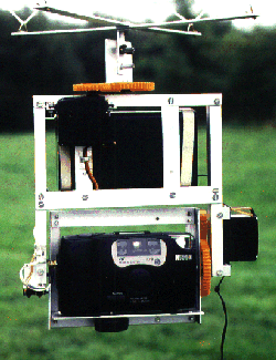
The frame was build as small as possible with alloy-profiles with a thickness of 1mm and 1.5mm. The remote-control receiver, the electronical switch to release the shutte of the camera and the power supply are fitted in a closed plastic box. The horizontal and vertical direction are set by modified servos which turn without limits. I use to gear disks to reduce the turning speed and to couple the turning elements. because of the cable for the shutter release, the vertical direction is limited in each way by a micro switch, which shut off the current of the servo motor only in that direction. The other turning direction is not affected. To release the shutter of the camera, I use a selfmade electronical switch for RC-receiver with a small relay. By closing the switch the camera starts a photo.
The first pictures with this camera station were made in the year 1993. With different suspensions I used this rig until spring 1995.
Using this systems I recognized the following items:
In spring 1995 I decided, to build a second camera station for universal use. This one should be able to carry the compact camera RICOH FF9, the reflex camera RICOH KR10 with an external winder and the video camera AKAI PV-MS8.
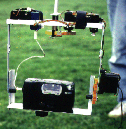
For the frame I used small alloy profiles with a thickness of 1mm. The upper part is built as a carrier for battery, receiver and release parts for the differnet cameras. The electronical switch with relay for the compact camera, the power switch and a voltage regulator was mounted in a servo housing. The shutter of the reflex camera is released by a wire driven from a servo. The video camera has no control, it will be started before the system goes up the line. The upper part of the rig was build smaller, but the carrier for the cameras had to be larger. With different fixing points it is easy to adapt the system to different camera types. The elevation of the camera is set depending to the way of the servo. With a potentiometer on the transmitter I can see the elevation of the camera directly. In the upper part of the rig is the axis for the suspension. The speed for horizontal direction is slowed down with a small gear. There is no control for setting the horizontal direction.
On Fanö I used this system the first time for the video camera. In autumn a test with the reflex camera failed, because the wind speed was to small.
Using this systems I recognized the following items:
Since 1993 I take aerial photos with radio-controlled camera stations. If you want panorama pictures from some photos togehter, it is difficult to set the horizontal direction correctly. The camera is turned to much and the photos do not fit together or the camera is turned less and the overlay of the photos is too much.
At the first international KAPWA-Meeting in Germany (Eastern 1993 in Bad Bevensen) I saw the camera station from Michel Dusariez, which he used to take panorama pictures. The camera station turns without remote control and stops after one complete turn. The photos are taken during the turn of the station.
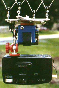
In february 1996 I started with the developement for the electronic of such a camera station. After pressing a start button, the electronic waits for about one minute. This time is for setup the camera station on the altitude for taking pictures. Than the motor starts for about one second to leave the stop-position on a control table. The motor turns the camera station until the stop-position is arrived. All my camera stations have a power switch. With turning on the power supply, the control unit for turning the motor must not start. The trigger for the camera RICOH FF9 (Shotmaster) will done with another switch pressed during the turn of the camera station. The electronic circuit for turning the motor is made in SMD-technology. The test of the electronic circuit was successful. After the time for setup the motor starts for a short time.
In april 1996 I made the mechanic of the camera station. For the turning of the system I use a modified servo which turns with no limits. Therefore I had to dismount my firs rig (*1992, +1996, that is life). I took out the electronic unit for radio control, because I only need the motor with the gear. The motor was connected with the motor control unit, which is placed wth the power switch and the start button in a housing for servos. For the power supply I use a 9V battery and the voltage is internal reduced to 5V. To fit all parts together I want to use less metal as possible. To fix the suspension I use a screw M4, which held the control table too. The control table depends on the size of the turning unit. My control table has a diameter of 100mm and is made of a board for electronic prints. On the control table are two levels with switch positions. One level has one switch position to stop the motor drive. The other level has eight switch position to trigger the camera in an angle of 45 degrees. For one turnaround the camera takes eight pictures. The camera is fixed top down to the camera station. The vertical is manual set by fixing the camera.
For the suspension I use a cross of alloy with a diameter of 100mm and the rigging type Rendsburg (from Ralf Beutnagel). The package for suspension and camera station without the camera is a box with the size 100mm x 100mm x 100mm.
The test of the system was successful. After the waiting time the motor starts to turn the camera station one time until it arrives the stop position again. The trigger for the camera (FF9) did not work correct. The speed of turning was too fast. The camera need some time to take the photo. Leaving the switch position it stops the trigger.
I had to develope a second electronic to reduce the speed of the motor. Because of the reduced speed the time for leaving the stop position have to be longer.
On June 21th, 1996 the system had its maiden flight. I used the RICOH FF10, because it fits better to the camera station and you can change the focal distance (38mm to 60mm). I used 60mm. The weather condition were not the best. It was a clouded early evening and sometimes the slow wind let the camera station sink. The kite was a flowform (Jim Rowlands). Some pictures were very good. With the focal distance 60mm only some photos fit to a panorama picture. The camera need not always the same time to take a photo.
The function of the camera station is good. I worked out a new electronic circuit to slow down the speed and to increase the torque of the motor. A reduction of the suuply voltage is not nescessary. The new circuit fits with power switch and start buttom in one housing for a servo. In october 1996 I connected this new electronic circuit to the system.

This photo session was made during the kap meeting in Bad Bevensen (FLiBB 1996).
In february 1997 this rig with radio-controlled functions was build as small as possible for the Ricoh FF10. It can also be used for the Ricoh FF9. The latest rig with remote control (number 2) was too big, because of the universal usage for compact camera, SLR and video-camera. To realize this small rig (over all: 15cm x 17cm x 4cm) the camera is mounted upside down.
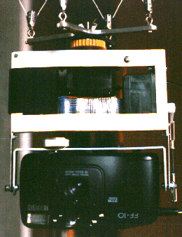
For all rigs with radio-control I use my system Graupner 314. For fast changing the receiver all needed signals are wired to a SUB-D9-connector (seen from Peter Bults). The horizontal direction is set by a modified servo (standard size) with endless turning. The vertical direction is set by an unmodified servo (standard size) with a push rod. So the camera can look from straight down (-90 degrees) to nearly +10 degrees to the horizon.
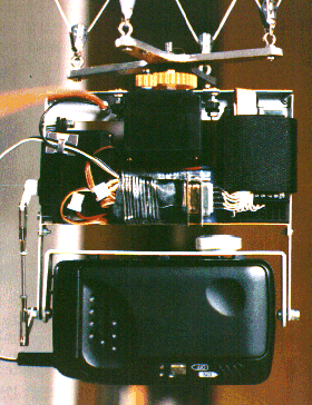
The shutter release is activated by an electronical switch in SMD-technology. The size of the circuit with the Sub-D9 connector for the receiver and the connectors for the two servos has the size 4cm x 2cm x 1cm. Power-on will done by connecting the battery (4.8V, 300mAh).
It is the first time, I took the weights of my rigs. This rig with suspension and camera has a weight of about 640g. The maiden flight of this rig was successfully done in the beginning of march.
[ Index ] [ Contents ] [ Top of Page ] [ Next Page ]
©2015 Harald Prinzler