
In this section I give a short description of all flowforms I know with the source reference. The sequence of description is about the time I worked on that kite.
In the book from Jim Rowlands is a building plan for this flowform. It is made of 8 chambers and 5 keels. With the two rows of bridle lines the angle of attack is changeable.
Compared to other flowforms Jim Rowlands use on his flowforms large profile height and inlets. The leading edges of his flowforms (less than 90 degrees angle) look different to all other flowforms (allways 90 degrees angle).
Depending on relationship between width and length this kite is a powerful lifter. The aspect ratio is more than one, but it is a stable flier. But sometimes it turns to one side and fly with stable direction until it hits the ground after very long time.
For building this kite use these notes:
In the book from Jim Rowlands is a plan of a smaller flowform. It is made of 4 chambers, 3 keels and one row of bridle lines.
The center chambers have a larger height as the outer chambers made by a different profile form. Therefore the fabric for the center top side is curved and difficult to build. The relationship about height of profile, height of inlet an keels is like the other flowforms from Jim Rowlands.
Flowform junior made by Peter Bults: Although it is a simple kite it is a great flier in stronger winds. He uses this kite for kite aerial photography.
In this plans are errors, too. Take care by building this kite.
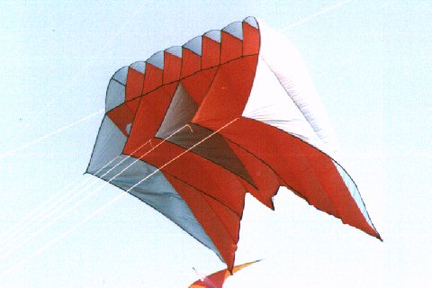
In the book from Jim Rowlands is a plan for a whale, based on his flowform constructions with longer profile and added flukes and flippers. The kite is built by 4 chambers, 3 keels and a bridle in 2 rows.

The relationship of profile height, inlet and keel are like the other flowforms of Jim Rowlands.
The whale is not a stable flier. It is not to fix at an anchor and leave flying alone. But for this kind of kite the unstable flying is ok.
The distances for flukes and flippers are missing. You can take these distances I have choosen:
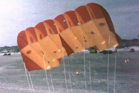
This flowform is based on the construction points of Jim Rowlands and made out of 8 chambers and 5 keels. The bridle in one row is made like the bridle of the flowform junior.

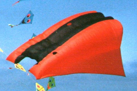
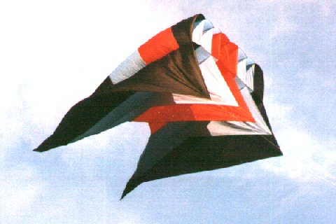
A plan to build this flowform is not published. On construction the outer profiles were made longer and gave that kite the V-shape on the trailing edge like a molar. In the middle of the trailing edge is a small tail which can be closed in lower wind speed and opend in higher wind speed. The maximum height of the profile is made larger than on flowforms by Jim Rowlands. Air flow holes on bottom and top surface were made later and increased the wind range a little bit.
In low wind speed this kite flies more stable a the flowform of Jim Rowlands. But in higher wind speed the flight is very unstable and it can fly to the ground of one side. These depends on the larger height of profile and so, this kite is only for slow wind speed. This kite has nearly the same size as the flowform of Jim Rowlands but the pull on the line is less. This depends on the on the bridle in one row, which not allows a change to angle of attack.
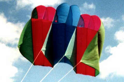
In the dutch magazine vlieger 93/2 this plan was published by Wim Houtman from Den Haag. This kite is made of 8 chambers, 5 keels and keels with an angle of 90 degrees on the leading edge.

All inner keels are made of one piece with one bridle line. The outer keels are made each of two pieces with 2 bridle lines and the angle of attack is changeable. The different length of the profiles form the V-shape of the trailing edge. Compared to Jim Rowlands is the maximum profile height lower. There are no air flow holes on top and bottom surface.

This flowform is made by Walter Bloem from Germany with a spanwith of 4m. The kite flies very well even with the large upscaling.
By a visit of an American kiter I got the chance to examine this flowform and to get some information for flowform comparison. The flowform has 4 chambers, 3 keels and bridle lines in one row. The leading edges of the keels have an angle of 90 degrees.
The upper side of the profile is curved over all the length from leading edge to trailing edge. Compared to other flowforms the maximum profile height is lower. The inner profiles are truncated far from the end of the normal profile. The center rib ends at the jet chute. All inner profiles have no vents. In my opinion the air flow across the chambers will work through the area at the trailing edge. Compared to flowforms by Jim Rowlands the aspect ratio is less than 1. The air flow holes on top and bottom side have al the same size.
Based on the examinations on the flowform #30 of Air Affairs I built this kite with a size of about 5sq.m (about 50 sq.ft.). The flowform has 4 chambers, 3 keels and bridle lines in one row.

The positions for maximum profile height and height of inlet opening are nearly the same as on the flowform by Air Affairs. The form of the profile is made by a hand made sketch ans is not so curved like on the flowform by Air Affairs. All inner profiles are truncated far from the trailing edge and the air flow between the chambers is done by the rear area of the kite. The jet chute is formed by sewing top and bottom side of the edges of the jet chute. On other flowforms this is made by complete inner ribs.
With truncating the inner profiles there was a large bulge in the rear area and causes too much lift near the trailing edge. To get the profile form near the trailing edge I inserted some pieces of lines inside the kite. Each line length depends on the profile height at the positions to insert the lines. With changing the length of the line a small change for the angle of attack is possible.
With only 3 bridle lines there is a lot of pull on each keel. Therefore this kite is only made for low wind speed. To handle larger drag in high wind speed it is better to make the keel out of two parts. The additional sewing will help to lead the drag through the keel. To make these parts cut the keel on a line at the half angle of the tip, where the bridle line is fixed. The drag of the flying line is held by this sewing line and the leading edge of the keel.
This plan is given in the book from Margaret Greger. The flowform is made of four chambers, 3 keels and a bridle in one row.
The form of the profile looks different against other flowforms. There is a relative small height over a long area. This shape of profile looks like 'the painless parafoil' from kitelines or 'Sorgenfreie Parafoil' from Drachenmagazin.
This plan is a smaller flowform published in the book from Margaret Greger. It is made out of 4 chambers, 3 keels and a bridle in one row.
The shape of the profile looks like other flowforms. I have heard, this kite is offered by Air Affairs under the name T-8.

These 'Fancy Pants' of Ray Williams have a spanwidth of 16 feet, a length of 19 feet and a height of 10 feet.
Carl Crowell published this plan on his web site in Internet. This flowform is made out of 8 chambers, 5 keels and a bridle in one row.
In the sketch the shape of profile and keel look like the flowform from Air Affairs. The maximum profile height and the distance of maximum height to the leading edge is larger. The trailing edge has a V-shape, made by different length of profiles.
In the plan are no exact information about the upper profile line between maximum height and trailing edge. Ther is no information about, who to make the inner profiles and the heights of their ends. In the plan are no air flow holes for top surface and bottom surface. Missing information can be read out of the sketches.
Because there are differences between the datas in the table and datas in the sketch of the flowform in the book from Jim Rowlands, Dan Weinreb changed the datas towards the sketch.

He published the datas of his profile form:
| X-Position | 0 | 5 | 10 | 15 | 20 | 30 | 40 | 50 | 60 | 80 | 100 | 120 | 125 |
| Y-Position | 22.5 | 26.0 | 29.5 | 32.0 | 34.7 | 37.48 | 38.86 | 39.21 | 38.17 | 31.27 | 20.13 | 4.34 | 0.0 |
Depending on the change of profile form the maximum height increased. The distance of maximum height to the leading edge is larger, too.
The french kite club Cerf Volante MIZTRAL published this plan on their web site in the Internet. This flowform is made of 4 chambers, 3 keels and a bridle in one row.
The shape of the profile and the keel look like other flowforms. The maximum height is larger and placed nearer to the leading edge. On the top side the air flow holes are only on the outer chambers placed.
It is not possible to get missing information from the sketches. There are no information about the profile height between maximum profile height and trailing edge.

This Flowform is made by Artur Pawletko with some changes to the inner profiles.
In the dutch magazine vlieger 90/6 this plan of flowform is published by Fred Drexler and Herman v. d. Broek. The building plan with exception of the size is nearly the same as the plan in the vlieger 93/2. On later examinations are the main differences between these flowforms found.

The upper profile line have different length with maximum profile height regarding on the length of the profiles. So the position with the maximum lift depending to the distance to the leading edge should be differnt on each profile. This may be a reason for the 2 bridle points for the outer keel. Shortening the rear bridle line should lead to a position of maximum lift nearer to the leading edge.
The plan has only few information to get the shape of the profile. The missing information can be read out of the sketch.
The airflow holes on top side and bottom side are not in a V-shape like on other flowforms. There are more holes placed in several rows all over the bottom surface. There are no holes on the upper surface.

This flowform is made by Tony Fitchett from New Zealand with a spanwidth of 4m. For better flight he changed the lower keel points 10cm towards the trailing edge.
In the magazine Kite Lines this plan of a flowform was published by Margaret Greger and Ed Grauel. It is the same as the flowform I in the book of Margaret Greger with only very few changes.
This flowform is made of 8 chambers and 5 keels and has no straight trailing edge. The keels are made of more than one piece to lead the drag better to the canopy. On the keels are bridle lines in one row.

This flowform was made in the beginning of the year 1999 to avoid problems by upscaling the American Flowform. The profiles are calculated and after the first flight corrected by hand. The top side of the profiles are curved on the complete length and the profile height is smaller to the relationship of the American Flowform.
[ Index ] [ Contents ] [ Top of Page ] [ Next Page ]
©2015 Harald Prinzler