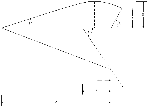
From all flowforms I know, I took specified datas for comparison. I scaled the main profile and the main flare to a specific length of the base line of the profile. All measures are related in percent to this base line.

These flowforms I used for the comparison with the given abbreviations. I heard about other flowforms and similar kites, but I have no information about them for comparison.

After I made sketches with the same relationship I took the information for comparison from the sketches into the following tabel. These information were already published in the first edition and will not be used in further examinations.

To get more exact information about the flowforms I calculated the datas for the comparison with the given information of the building plans. Against the first edition I used everytime the outer profiles and the outer keels for the comparison.

After making sketches from all known flowforms in a relative size, I could compare all flowforms together. The flowforms can be aranged in three categories. Some flowforms have details from more than one kategory.
Flowforms based on Jim Rowlands
Flowforms from Jim Rowlands have a large profile height, a straight course of
profile to the trailing edge and a keel, which leading edge has not an angle of
90 degrees. The distance of maximum height of profile to the leading edge is
larger. In stronger wind there can be too much lift and the angle of attack may
be too low. The flowforms with bridle in one row can collapse by pressing down
the top side of the inlet opening. With a bridle in 2 rows the angle of attack
can be changed to reduce the lift in higher wind. On my own, I had until now no
problems with collapsing by closing the inlet opening.
Sutton Flowforms
This named flowforms are all made out of 4 chambers and 3 keels. The course of
profile on the top side is curved from leading edge to trailing edge. The
maximum height is placed nearer to the leading edge. The leading edge of the
keels have an angle of 90 degrees and have a bridle in one row. With a lift
more to the leading edge the angle of attack can not increase too high and the
kite will fly stable even if there is more wind.
In some plans the maximum height is too large and set to far from the leading edge. In gusty wind some built flowforms flew unstable and collapsed.
Flowforms with curved trailing edge
The curved trailing edge is made by different profiles or by changed course of
profiles to the trailing edge. Most times the outer profiles are longer as the
inner profiles. Depending on the normal size of profile the distance of maximum
height to the leading edge is larger and will cause more lift for the longer
profiles.
If all profiles have the normal size the aspect ratio would be larger than one. That may be a reason for a powerful lifter with longer profiles for stability.
The base for this examination are the information I found about profiles for air planes. On those profiles the position of maximum profile height is most times at 30 percent of the profile length. On the profiles of the flowform I used the distance between position of maximum profile height and trailing edge for 70 percent of the profile length. With these information I calculated the theoretical complete profile length and the related profile height. I used the calculated datas of flowforms for the examination.

[ Index ] [ Contents ] [ Top of Page ] [ Next Page ]
©2015 Harald Prinzler