|
Harald Prinzler Mikroelektronik, Fesseldrachen und Fotografie |
Detmolder Straße 93 D-33175 Bad Lippspringe Phone: +49-5252-7830 email: harald@hprinzler.de URL: http://www.hprinzler.de |
Flowform FF04A
The flowform FF04A is a modified version of the FF04 (Molar shaped Flowform). The keel height is reduced to get a stable flight even in larger wind speeds. The height of the inlet is reduced to prevend possible folds on the upper leading edge.
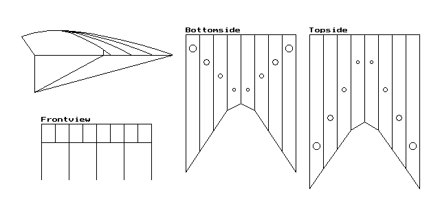
Like the FF04 this kite is built with 8 chambers and 5 keels, too. The 2 center chambers are open at the trailing edge (jet chute). The internal pressure exchange is made by holes on the inner ribs (vents).
All values are related to the base line of the profile (lower leading edge to trailing edge = 100). With the given datas you should calculate all pieces of the kite depending on your chosen size. The length of the base line should be 2 metres or more.

All profiles are made complete, except profile P5, which is formed like the profile P4 with a cutted trailing edge.
P1              P2              P3              P4              P5
Xp      Yp      Xp      Yp      Xp      Yp      Xp      Yp      Xp      Yp
--------------------------------------------------------------------------------
0       0       0       0       0       0       0       0       0       0
-9.453  13.515  -9.453  13.515  -9.453  13.515  -9.453  13.515  -9.453  13.515
-8.250  14.048  -8.250  14.048  -8.250  14.048  -8.250  14.048  -8.250  14.048
-5.243  15.166  -5.243  15.166  -5.243  15.166  -5.243  15.166  -5.243  15.166
-2.236  16.035  -2.236  16.035  -2.236  16.035  -2.236  16.035  -2.236  16.035
0.000   16.551  0.000   16.551  0.000   16.551  0.000   16.551  0.000   16.551
3.778   17.213  3.778   17.213  3.778   17.213  3.778   17.213  3.778   17.213
9.792   17.824  9.792   17.824  9.792   17.824  9.792   17.824  9.792   17.824
15.806  18.005  15.806  18.005  15.806  18.005  15.806  18.005  15.806  18.005
21.820  17.846  20.748  17.846  19.677  17.846  18.606  17.846  18.606  17.846
27.833  17.409  25.691  17.409  23.548  17.409  21.405  17.409  21.405  17.409
39.861  15.882  35.576  15.882  31.290  15.882  27.004  15.882  27.004  15.882
51.889  13.690  45.461  13.690  39.032  13.690  32.603  13.690  32.603  13.690
63.917  10.992  55.345  10.992  46.774  10.992  38.203  10.992  38.203  10.992
75.944  7.869   65.230  7.869   54.516  7.869   43.802  7.869   43.802  7.869
87.972  4.343   75.115  4.343   62.258  4.343   49.401  4.343   49.401  4.343
93.986  2.420   80.058  2.420   66.129  2.420   52.200  2.420   50.000  3.941
100.000 0.378   85.000  0.378   70.000  0.378   55.000  0.378   50      0
100     0       85      0       70      0       55      0       0       0
0       0       0       0       0       0       0       0
Vents on profile:
Profile Xp,Yp   Diam.   Xp,Yp   Diam.   Xp,Yp   Diam.   Xp,Yp   Diam.
        (Vent 1)        (Vent 2)        (Vent 3)        (Vent 4)
-----------------------------------------------------------------------
P1      (no vents)
P2      20,7    10      35,7    10      50,6    8       65,3.5  3
P3      20,7    10      35,6    8       50,4    4       -
P4      20,7    10      35,5    6       -               -
P5      20,7    10      35,5    6       -               -
The outer keels (K1) have a length like the base line of the outer profile (P1). The inner keels (K2) have a length like the base line of the center profile (P5).
K1              K2
Xp      Yp      Xp      Yp
--------------------------------
0       0       0       0
0       -27.008 0       -27.008
100     0       50      0
0       0       0       0
Length: 100 (theoretical)
Width: 80 (complete)
Chamber width: 10
Length of pieces for surface:
C1U:            100
C2U:            85
C3U:            70
C4U:            55
Air flow holes:
The air flow holes are placed in the middle of the chamber width on the given
distance to the leading edge of the bottom surface.
                C1U     C2U     C3U     C4U
------------------------------------------------
Distance LE     10      20      30      40
Diameter        5       4       3       2
Length: 112.193 (theoretical)
Width: 80 (complete)
Chamber width: 10
Length of pieces for surface:
C1O:            112.193
C2O:            97.638
C3O:            83.305
C4O:            69.404
Air flow holes:
The air flow holes are placed in the middle of the chamber width on the given
distance to the leading edge of the top surface.
                C1O     C2O     C3O     C4O
------------------------------------------------
Distance LE     80.907  60.585  40.191  20.037
Diameter        5       4       3       2
The trailing edges of the chambers C4 are open. Cut the surfaces between the ends of the profiles P4 and P5 on a straight line. All other trailing edges are closed.
Bridle line: 1.0mm polyamide (for 2 metres spanwidth)
B1      B2      B3
------------------------
200     201     204